G'day everyone, this blog is my journey and experience with purchasing and restoring my favourite computer of all time, the Amiga 1000, and hopefully will help other people in their journey too. My experience would see parts delivered from 9 different countries across the globe, and has been 4 months in the making.
Disclaimer: There is no sponsorship or payment in kind, and all comments are my own experience / opinions unless stated otherwise. I am a private individual member of the public, I am not a business, nor am I representing any business. This blog is not to be taken or used as advice or instruction, replicate at your own risk. I have destroyed 1 x accelerators, 1 x GOTEK drive, and possibly 1 x Amiga 1000 (at time of writing) in my adventure so far 😅
Practice Session:
After scouring through PCBWay, and all the warnings about Electro-Static-Discharge shocks killing CIA chips (8520's), I came across an interesting mod for ESD protection. If you are planning any SMD work, do yourself a favour and purchase a video microscope and an SMD tweezer kit, pliers are too big, and the microscope is essential to see what you are doing.
 |
| Great practice, a large few grains of sand? |
 |
| The finished product |
 |
| Installed on the Amiga 1000, but not a good fit |
After building the board, it sits over the top of the existing DB9 pins for the mouse and joystick. However, it does not sit well, even after heating up the solder. I found my mouse and Joystick did not work with his mod, and removed them. Once removed, the mouse and joystick worked fine again. The practice however was great preparation for working on the Amiga 1000 mainboard as what before seemed tight, was now ample space to work within.
In hindsight, maybe I could have desoldered the DB9's to ensure the maximum pin-length was available for the ESD board to sit on and maybe I would have a better connection.
Joystick or Woestick?
Anyway, after taking the ESD mod (above) off, I was still having bizarre problems with a Wico 'Command Control' joystick I had also purchased on eBay. The joystick would permanently move to left, unless I pushed the joystick to move right, then it would stop!
So much for the 'testing' promised in the advert (my advice, beware of all Amiga eBay purchases. Amiga has become so lucrative, people will sell any rubbish at ridiculous prices, ignore all promises of 'working' and expect everything to be faulty at the outset and needing repair). Anything labelled as untested or 'was working' is almost a guarantee that it is no longer working.
 |
| Wico "Command Control" after a thorough cleaning...it too arrived filthy from eBay. |
At the same time, this was when I was having problems with the Amiga still not booting, and giving me a black screen. This was resolved with replacing my EVEN CIA chip. See below for more on this. But my joystick problems remained.
I really doubted there was a problem with the joystick as they are such simple devices, just a few switches and wiring. Further assistance sought from Mr. Dunklee:
The Joy/Mouse movements are multiplexed by a device at U1T (PAL Motherboards) or U1M (NTSC Motherboards), the 74LS157, and then sent to the DENISE. The 8520’s only control button presses. The orthogonal movements are not traditional ON/OFF (+5V, 0V). They’re state changes multiplexed by the 74LS157. I suspect that’s why the ESD didn’t work as the ESD is likely filtering out the very changes needed. You should be able to trace the lines from the ports to the U1T device (they go through a network of caps/resistors). I’d connect the joystick to the port and then test if the inputs are working to the U1T (in other words… check resistance between the pin on the port and the pin on the chip… should be 220 Ohms if I’m reading the schematic right. If you get infinite or well beyond 220Ohms, then there’s the problem. Here’s a schematic… this is for the NTSC Amiga and thus the chip/resistor/cap naming is all off for PAL boards… but it’s still the same logic… especially around the joystick area… So… for example you should be able to check if you get a signal from the Left Joystick (0) pin 1 (Forward0) to pin 3 on the 74LS157 (Your U1T)… repeat for the other 7 signals. If you don’t get input/continuity from one of these signals… the flaw is somewhere between the two points. If not… the flaw is between the 74LS157 and the Denise…

So I went about removing 74LS157 at U1T, you can find more about this chip here.
 |
Use LOTS of flux! Go ahead, add another dollop.
|
 |
| Target Acquired: 74LS157 at U1T |
Removing anything from the Amiga 1000 mainboard is really tough. These are old-school 4 layer boards, it takes a long time and a lot of heat to get solder to flow. You cannot use enough flux!! It took me maybe 2 hours to remove this one little chip. And even then to clean up the holes, I committed a cardinal sin and used a needle thin micro-drill bit along with my soldering iron to clean out the hole. The soldering iron heated up the solder, while I pushed though with the micro-drill.
NEVER EVER DO THIS!! This was careless and reckless in hindsight! There is a small copper sleeve that connects planes of these 4 layer boards, and if I had damaged that, the board would have been stuffed - likely beyond repair!
 |
| Just call me 'The Butcher' |
 |
| Close-up of my butchering |
 |
| I lost some solder pads in the process, but was very lucky it still worked when solder was re-applied. |
I used a socket to make re-inserting the new IC easier, however this was a mistake as the chip then sits too high and interferes with the floppy drive spinning!!
As I did not want to de-solder again, I replaced my floppy drive with a. GOTEK drive using the HxC firmware and hardware mod to display floppy images on-screen, removing the need for an OLED/LED to hang out the floppy drive slot, and no need for any new holes in the case.
 |
| Socket added, IC replaced with a new 74LS157 |
 |
| Looks even better when the flux is all cleaned away using IPA/Isoproply |
While that was fun, and a good heads-up/practice for what was coming when I perform the Parceiro ROM mod, it did not fix my joystick problems, aghhhh!
This left troubleshooting to the joystick and cable as the problem. I had already tested the leaf-switches in the joystick with the continuity setting on my multimeter. They all connected fine when activated and the multimeter buzzed appropriately.
I would check I had continuity after connecting each wire. I really went about this "the hard way" and after 3 unsuccessful attempts at fixing the cable, I purchased a new cable off eBay (which I should have done from the start and saved myself not only $$, but time too. Still, the learning was worth it).
 |
| After cutting the cable, I was trying to join wires and insulate them again with heat-shrink wrap. |
My first attempts failed due to incorrect wiring, and using the wrong DB9 connector - the kind you buy at your electronics store won't fit into the Amiga 1000 DB9 port correctly and keep popping out. They need to be lighter, with longer end-connectors. In other words, buy a proper replacement joystick cable!
 |
| Now I had a proper replacement cable, I removed the old cable and wired this straight to the switch wires. |
I found Michael Steil's site on pagetable helpful for working out which wires and pins connect to each other. And since this Wico Joystick had 2 buttons, I also wired the second button to pin 9 which gave me a button 2, rather than just a boring (and unlikely to be used) alternate for Button1.
Having a second fire button is great in Turrican! You won't go back once you have tried it!
Success!! I have a working and improved joystick!!
What's better than owning an Amiga? Owning two Amigas!!
During this time, another Amiga 1000 came up for sale in my country, and this one had the keyboard and mouse! As a risk mitigation strategy, having a spare Amiga 1000 would give me peace of mind against something failing.
 |
My regular PAL Mainboard, with my electroplated clock shield.
"Hey there Ms. Looking-So-Good!!" |
I could harvest parts from a spare Amiga, especially the Agnus (8367R0) chip. Replacing the Agnus in an Amiga 1000, would mean buying buying another Amiga 1000 anyway (I am yet to see an Agnus 8367 come up for sale, plenty of the later versions used in the A500's etc which is the fat Agnus, 8370 and 837x series, but the A500 used a PLCC (fat), not DIP (thin) package and PLCC will not fit in the A1000). This is the same reason we are limited to 512KB Chip RAM, our thin Agnus can not address above 512KB. To-date there is no way around this on an Amiga 1000.
I liked this wikiwand description of
Agnus.I am really hoping an FPGA solution is invented to replace our thin Agnus one day, and maybe even lift our 512KB chip-ram limit finally. With my 2nd Amiga 1000, I could now select the best components from each Amiga to build the best one from the two, and if they both worked I have a test machine to help troubleshooting with. Well, that's what I used to convince myself to buy another Amiga 😎
It turned out, the second Amiga was one of the rare daughterboard PAL Amiga 1000's! Woohoo! Not an exact replacement for my PAL Amiga 1000, but perhaps even better! This daughterboard Amiga I would keep as close to stock as I could due to its rarity (and most accelerator boards will not fit in it anyway as the daughterboard is in the way).
Daughterboard PAL Amiga's were only sold for the first few months of the Amiga 1000 release and are considered rare. The daughterboard Amiga's are actually a modified NTSC Amiga. The RCA Video out is still marked as NTSC on the mainboard silkscreen.
I did perform the Parceiro Kickstart mod...It's a quality of life improvement. The mod to enable the Kickstart feature of the Parceiro II looked easier to perform on the Amiga with the daughterboard, so I started there.
My Parceiro arrived, I was very excited, and would not be disappointed! The current Parceiro provides 3 kickstart ROM Banks, and one kickstart-ROM-disabled bank so you can still use a Kickstart disk if you choose/need; also:
- a Real-Time-Clock
- 8MB FastRAM
- and a bootable SD-Card Hard Drive (32GB, but the image only needs 16GB).
The Parceiro also comes with software to load kickstarts and to format your SD Card for the Amiga (including both MBR and RDB so you can boot your Amiga, and at the same time have a partition formatted as FAT to enable very easy sharing/copying of files over with your Mac or PC. The ROM-Banks and the FAT partition are life-changing must-haves, you will never go back!
The Parceiro is essential for any Amiga 1000 owner. The ability to not need a kickstart disk is life-changing, and everything else it comes with, is just the AWESOME in awesome-sauce! David is still making them, and working on the next model, which he also offers upgrades to existing owners - the guy needs a sainthood!!
To top it off, the install instructions are really top notch! The soldering work needs some basic soldering skills and at least some experience. The right tools make all the difference here!
The super-fast SRAM FastRAM used gives your Amiga a slight performance boost, just by plugging The Parceiro into the Amiga 1000's side expansion!
I also ordered a 68010 with mine for just a tiny bit more pep and to use the quit key with WHDLoad/JST, which a stock 68k sometimes needs a reboot for. David Dunklee's comment on this:
"As for differences between a 68000 and 68010... the primary difference is:
- Movable vector base on the 68010 (to allow for virtual memory management)
- The requirement to be in Supervisor mode to move the condition code registers from the stack (again, a condition for memory management).
- A 6-byte instruction cache which makes specific loops twice as fast.
- Improvements in the multiply and divide microcode that, again, make these instructions faster. (But the results remain the same)."
All this enhancement also works in Workbench 1.3 too! The Parceiro is a rare upgrade that has been designed with Workbench 1.3 in mind, but also works with Kickstart 2, 3, 3.1 and Kickstart 3.2.1 and now, I could not use the Amiga without it!! Flawless perfection.
 |
| SysInfo speed test with 68k CPU and Parceiro |
 |
| SysInfo speed test with 68010 CPU and Parceiro |
 |
| SysInfo Drive speed test with 68010 CPU and testing the Parceiro SD-Card |
With a 68000 CPU, I was seeing Drive speed tests from the Parceiro of around 400KB/sec, and with the 68010 CPU about 100KB faster at around 500KB/sec. That's a whole lot faster than the Amiga floppy drive which transmits data at about the same speed as a 9600 baud MODEM (about 0.96KB/sec for you kids reading this)!!
 |
| Parceiro II, GALs, and the wire |
 |
| This is a really well made unit! |
 |
| The silkscreen names are gold-topping on an already awesome product! Take the time to read them, and enjoy! |
Modding for the Parceiro ROM feature:
This mod requires adding a single wire and the replacement of two PAL chips (not the video standard, in this context, PAL stands for Programmable Array Logic) wi
th two GAL (Generic Array Logic) chips. s100computers advises:
"GALs combine CMOS and electrically erasable (E2) floating gate technology to yield a high-speed, low-power logic device, they essentially replaced PAL's over time".
David Dunklee supplies high quality DIP Sockets and the pre-programmed GALs with the purchase of the Parceiro 2. If you have a programmer, you can also program your own. At the time that I purchased my Parceiro (~September 2022), David was supplying a pair of Mill-Max 115-47-320-41-001000 20-pin sockets for the PAL mod.
"...They’re the best in my humble opinion. I also use GAL16V8s instead of PALs 16L8s. Do you have the ability to burn your own PALs/GALs? Maybe you have a TL866II programmer?" - David Dunklee 2022.
With my recent 74LS157 replacment experience, and subsequent purchase of an SMD re-soldering station I was ready to start something I never had the courage (or time) to do until now.
Another disclaimer: These are not a replacement for David Dunklee's instructions, you must use his instructions! This might help you on your journey, or in a moment of hopelessness - all is not lost, and a good night sleep often just made things work the next day (I have Mr Dunklee to thank for that advice, which was proven true many times on this project).
Step1: Remove the daughterboard. There are three screws, and then carefully wiggle it up and off the many extra-long pins the daughterboard sits on and connects to the mainboard with. If you have the more common single-mainboard PAL Amiga 1000, you don't have to worry about this, yippeee!
 |
| Safely removed, the underside of the daughterboard |
 |
| The mainboard hidden under the daughterboard |
Step2: Using
heat resistant tape to protect IC components (DAUGEN, DAUGCAS) around the area I would be working on.
Purchasing something to hold the PCB while working on it does make life easier, especially when you have a hot-air gun in one hand, and pliers in the other trying to extract the chips!
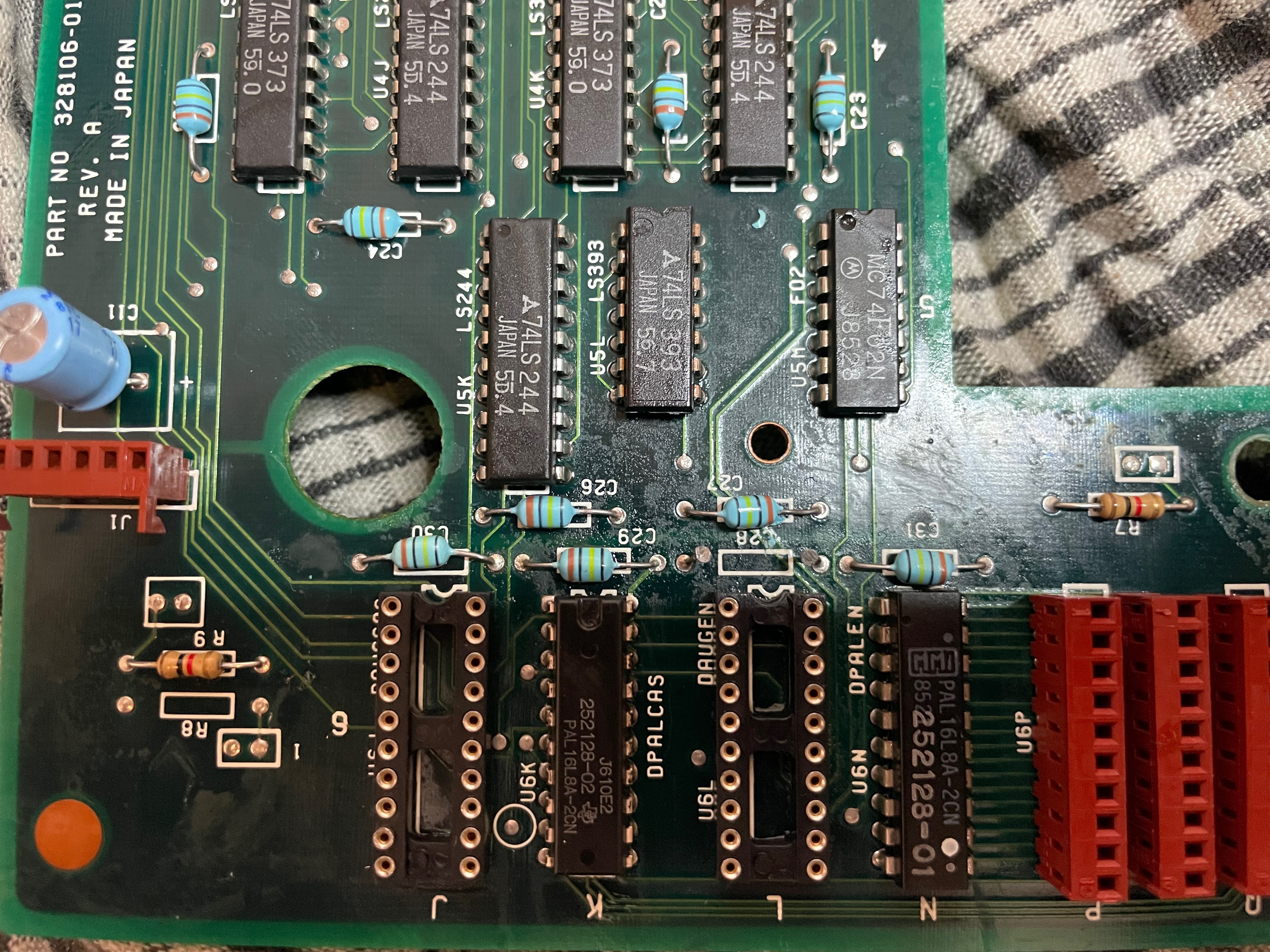
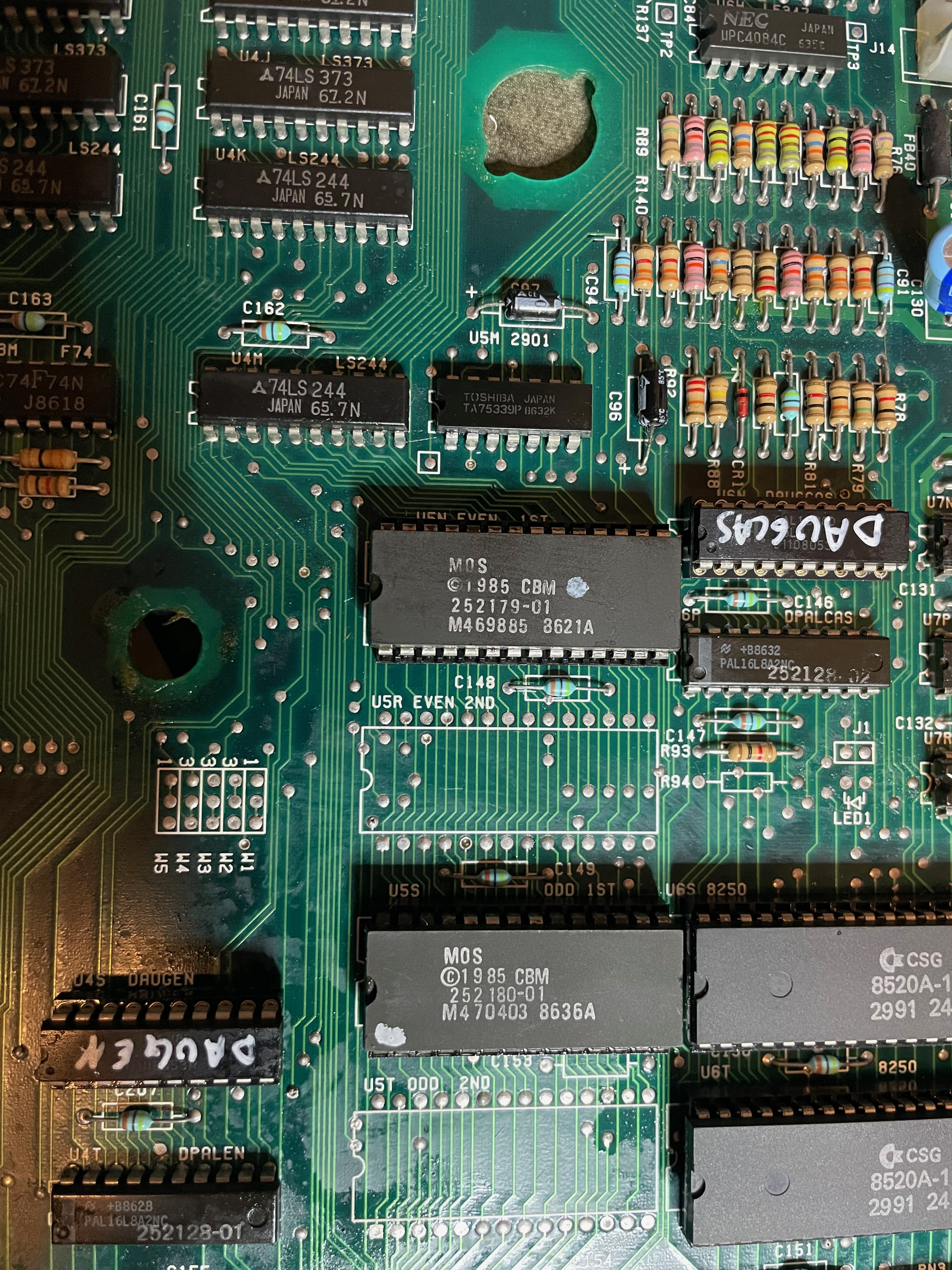
Rather than repeating all this again, here is the single-board Amiga all prepared for the same modification and chip extraction, note the two chips to be replaced are not as conveniently located near one-another as they are on the daughterboard. Take your time, landmark them with a marker-pen so they are easier to find once you look away:
 |
| Regular PAL Amiga 1000 Mainboard |
 |
| You can't apply too much flux, go ahead and add more! |
Step3: It took me about 6 hours to extract each chip. Heating with the hot-air-gun set to 390 degrees celsius, and the soldering iron set to 350 degrees celsius. I would swap between using the soldering iron and desoldering-wick and a solder sucker, and then using the hot-air station while gripping the IC with a set of pliers and somewhere between gently and firmly pulling on the chip. I'm sure there is a better technique, this was my first time. Oh and lots and lots of flux!!
I really envy the folks that have those de-solder guns! It looks infinitely easier than my Neanderthal technique! And so much safer for the Amiga 1000!! I can't find one locally, but it's on my list now for an online order in 2023!
Slowly the chip loosened and eventually came free! I could then use the solder wick again to clean-up the holes, ready to replace with a socket. The first chip I removed, was again a butcher job:
 |
| Sometimes, the love is too much.... |
I got better as I went, and extracted the other chips without damage. The first one was hardest because I did not know what to expect or if I was doing it right...we're still talking about extracting IC's right?
 |
New and shiny...Hey! Something is missing....
|
Hang on just a minute...Notice anything missing just above the DAUGEN socket?
Lesson learned - do NOT use the hot-air on the component/chip side of the mainboard!! I disintegrated... No. I totally blew out of existence, a capacitor. Even with the heat-deflecting tape (the hot air was escaping under the tape).
Actually the capacitor in front of it was broken too, but luckily both were easily replaced with a ceramic 0.1uF capacitor (Thanks again for Mr Dunklee's advice while I had a small panic). I could not find the in-line type of capacitor, but that didn't matter, I just needed the right value in a ceramic cap.
Unlike electrolytic capacitors, ceramic capacitors don't leak and usually do not ever need replacing, unless they are murdered by a sadistic, hot-air-gun wielding, maniac butcher....
 |
| Replaced the two capacitors I exterminated previously... |
And then, the new GALs:
Step4: Just one more step now, the wire.
This was tricky, it is a very small spot to connect too, but I also discovered at this time,
solder-paste!! Solder paste is once-again, life-changing!!
You take a tiny amount with your tweezers or the tip of a scalpel knife, and place it around your component. It comes out of the tube with the viscosity of toothpaste, but do not try brushing your teeth with it. Please don't!
Place the wire, next to the component/solder point, and into the paste, stick your soldering iron into the paste, next to the components and in seconds the paste 'bubbles', creates tiny solder balls, which quickly melt and flow around the joint. So much faster than traditional solder, so much cleaner and easier!!
To clean up, use IPA / Iaspropyl and a toothbrush. Dry off and admire your magnificent work!
 |
| The first solder point done |
 |
| All three solder-points done, and a spot of hot-glue at each point for extra protection (not required, I just have a thing for hot-glue) |
 |
| And do it again, on the single mainboard PAL Amiga 1000 |
 |
| This one was a little more tricky, but with patience and zen calm, its easy |
 |
| And the finished product. Whoop! Whoop! |
You could just use straight lines and minimise noise, but it's not a signal line (not carrying data) so noise does not matter. The right-angles made it easier for me to find the right solder-points, and is closer match to the instructions that come with the Parceiro.
 |
| Single mainboard PAL Amiga 1000 done |
 |
| Now that it is done, it looks easy....PAL Amiga 1000, single mainboard version |
 |
| Zoom out on the single mainboard PAL Amiga 1000 |
The soldering of this 'one wire' took me about half a day, a day in total for both Amiga's - patience and a calm mind helped get it right. They are very small points to solder to, not as small as SMD, but not a lot of room for error or spills. That solder paste and lots of flux really helped.
Again, David Dunklee's instructions are very good, plus David was very generous with his time on email to help hold my hand through. I can not thank Mr David Dunklee enough, and it was worth every minute!! Wot? I'm not crying...I just have dust in my eyes....😜
Finally, I could put the Amiga's back together for the first time in a couple months now!!
At the peak of euphoria, and anticipation I put them all back together and switched them...to....nothing...Oh-no!!
I thought for a while I had destroyed two Amiga's..all that time and then money blown that would need to be explained to the CEO (my wife) at some point....."Yes dear, you are right. I love you?"
Drama, drama...like David has reminded me many times, I just needed to go to sleep!
A1000 Boot Chime, Blown CIA's and Shielding Shorts:
As mentioned in my previous post,
I was getting
the startup-chime (side note, the startup chime is based on composer Richard Wagner's, Ring cycle):
 |
| Image courtesy of The Amiga Guru Book (Taunusstein, 1993); |
More on the A1000 Boot chime from The Amiga Guru Book (Taunusstein, 1993);:
In the boot ROM of the Amiga 1000, the concluding diagnostic performed is an audio test in the form of a short melody. This consists (more or less) of the Horn Motif from Richard Wagner's "Siegfried", the third part of the "Ring des Nibelungen", transposed four half-tones down (cf. [36, page 29]). The tones are output in sine form (64 samples) over various channels (cf. table 9.2).
According to Robert Peck, the diagnostic.routines of the boot ROM were written by a man called Siegfried "Dusty" Bleher.
 |
| Image courtesy of The Amiga Guru Book (Taunusstein, 1993); |
But my floppy drive was not activating (and no kickstart screen). As this blog entry is already so long, here is the short version:
This was a dead CIA 8520 EVEN chip (U6S on my PAL Amiga, U6N on an NTSC Amiga), which once replaced fixed that issue. The ODD/EVEN chip designations I found in the Phoenix Manual on amiga-storage.net.
 |
| CIA Chips, ODD is the one closest to the CPU, at the bottom on this pic |
Through this I learnt that the
CIA (8520) chips,
Denise (8362 R6, or if you have the R5 version - Daphne) and
Paula (8364) can be replaced with the same chips found on an A500 or A2000. Easy to find on eBay too, but check prices carefully as there are some jokers living a fantasy and asking hundred of dollars.
Another side note: a good interview with
Glenn Keller, the inventor of the Paula chip can be found
here.
 |
| The girls |
I also learnt a lot more about the screen colour codes that come up at boot time. From this list, I have now personally 'enjoyed' the experience of Grey, Black, Red, Yellow, White, Blue and Purple boots. Just Green to collect now.
The point here is, don't panic or be alarmed! I too had to calm-the-farm and take it one step at a time, and often the next day. I made so many mistakes due to long hours and late nights rather than just stopping. It's not the destination, it's the journey, and there is always another destination after this one 😆
The black screen was fixed with replacing the CIA chip and then later I found my Shielding was shorting the Amiga somewhere. Whenever I took the lid off for testing, it worked, put the lid back on - black screen. Ha! What a tease! While I never found the exact cause, taking it all apart and then reseating everything fixed that issue.
The CIA (8520) chips are identical and interchangeable. A common test is to swap each chip into the other socket, if the Amiga boots - you have found your faulty CIA chip. CIA chips are prone to electrostatic damage (which is usually from plugging/unplugging peripherals like joysticks, but anything from any port) while the computer is turned on. SO, what do the two chips do?
- 'Even' U6S (PAL) U6N (NTSC) CIA manages the floppy drive, serial, and some parallel port status
- 'Odd' U6T (PAL), U6P (NTSC) CIA manages the parallel port, keyboard, some support for floppy drive, and joystick/mouse button number one (Button 2 is read directly from pin 9 of the DB9 Joystick/Mouse port).
The other issues were either a chip not seated correctly, or I had not switched the ROM-bank on the Parceiro correctly into position. It took some time, but easily fixed. For easy reference to anyone reading this blog for help, here are the colour codes:
- Red - An error in the Kickstart rom as detected.
- Green - An error in the Chip Ram was detected.
- Blue - An error in the custom chip set was detected.
- Yellow - The CPU encountered an error before the system's error-trapping code (the code the calls up the Guru) was in place.
- Black - No CPU detected
- Grey - CPU Passed the test
- White - CPU failure
- Purple - Kickstart ROM error - Parceiro ROM switch not positioned on a ROM bank correctly, or set to no ROM when using an '030 accelerator (I've tested with a TerribleFire 536 and a 68030-TK2 - more on those in a later blog)
Further explanation from the "The Amiga Guru" :
The color codes in the event of failure:
turquoise (RGB==$OCC) - RAM failure in the Kickstart WCS (AlOOO only).
green (RGB==$OFO; pre-2.0: RGB==$OCO) ~ error in the lowest 256 kilobytes of Chip memory. This might also be caused by a defective CIA-A (memory overlay bit, for example) or Agnus chip.
yellow (RGB==$FE5; pre-2.0: RGB==$CCO) - an unexpected processor exceptionoc- curred during the initialization of the system, i.e. before the Guru was prepared. This color code can, by the way, also occur if the reset routine is entered from outside the supervisor mode (e.g. by a direct jump). On the A3000, this may be an indicator of defective hardware, as accessing "nonexistent" memory (or faulty hardware) may result in a bus-error exception.
red (RGB==$FOO) - invalid Kickstart ROM checksum (Kickstart 2.0 only, cf. sec- tion 9.2.3).
magenta (RGB==$FOF) - if the single-task (RTF_SINGLETASK) or cold-start (RTF_- COLDSTART) initialization through InitCode() has failed (Kickstart 2.0 only).
Enough again, next blog entry will look at the SD-Card, partitions, making backups and why HD ToolBox won't get you what you need (you must use SD Toolbox, supplied with the Parceiro).


No comments:
Post a Comment